
 个人中心
个人中心 退出
退出


OpenLayers 6 绘制高德导航路径的蚂蚁线样式并实现箭头动画——VectorContext的重度使用
OpenLayers架构之内提供了矢量对象样式化的一些手段,但平时的使用总感觉有一些单一;而像高德、百度、腾讯地图这样的框架有着美观丰富的UI样式。从接触OpenLayers开始,就一直有一起学习的朋友讨论如何做一个像高德导航那样的路径样式,这个需求确实在很多项目中也会用到。本文就针对这个问题进行一下详细介绍。

原版高德导航的路径样式
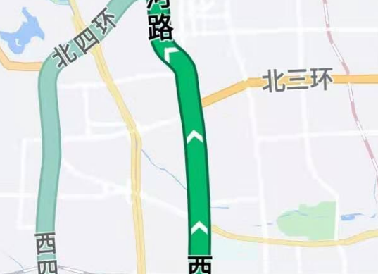
OpenLayers实现的动态样式
问题分析
稍微熟悉一点OpenLayers的开发者都知道,OpenLayers原生不支持这种带有小箭头类型的样式,所以需要我们自己造轮子。路径肯定是使用linestring类型的要素是没差了,此外还有几个问题需要研究一下:
仔细观察一下高德导航的这个路径样式,在路径的两边还有描边,OpenLayers的linestring是只有stroke而没有fill的,所以需要用不同颜色不同线宽绘制两次。起点和终点的两个点状要素同理。
箭头的方向会根据线段的方向变化,所以需要针对linestring每一个线段的走向,计算出相对y轴的夹角,作为箭头偏转的rotation属性。
高德导航里箭头之间的间距是可以随着缩放级别进行自动调整的,这个也好办,只需要绘制的时候以当view的resolution为依据就可以。
以上问题解决之后就可以实现基本的效果了,但是如果想要箭头变成动态的,还需要利用OpenLayers的render机制。可以在每一次渲染图层的时候,针对每一个箭头符号设置一个偏移量,然后显式调用map.render(),这样通过不断地渲染图层(底图因为revision counter没有变化而不会重复渲染瓦片数据)实现关键帧的切换,从而形成动画。
最后还有一个性能上的问题,因为要实现动画绘制箭头,需要不断地更新点位的信息,所以常规的VectorLayer满足不了需求,需要使用VectorContext直接在canvas上绘制。
代码实现
首先把需要使用的地图的基本结构搭出来:

import { Map, View } from 'ol';
import OSM from 'ol/source/OSM';
import TileLayer from 'ol/layer/Tile';
import LineString from 'ol/geom/LineString';
import Point from 'ol/geom/Point';
import VectorSource from 'ol/source/Vector';
import VectorLayer from 'ol/layer/Vector';
import Feature from 'ol/Feature';
import GeoJSON from 'ol/format/GeoJSON'
import { getVectorContext } from 'ol/render';
import { Fill, Stroke, Circle, Style, Text, Icon } from 'ol/style';
import soul from './data/soul.json';

let tileLayer = new TileLayer({
  source: new OSM()
})
let map = new Map({
  target: 'map',
  layers: [
    tileLayer
  ],
  view: new View({
    center: [11936406.337013, 3786384.633134],
    zoom: 5,
    constrainResolution: true
  })
});

var vSource = new VectorSource()
var vLayer = new VectorLayer(
  {
    source: vSource,
  }
)
var geojsonFormat = new GeoJSON();
var features = geojsonFormat.readFeatures(soul, {
  dataProjection: "EPSG:4326",
  featureProjection: "EPSG:3857"
});
var street = features[0];
map.addLayer(vLayer);
map.getView().fit(street.getGeometry());
这里使用的路径数据是官方实例中首尔的某些街道信息,使用了其中的一条。坐标系采用的是默认的3857。
然后缓存了一些样式对象:


//some styles =========================================================================
var textStyle = new Style({
  text: new Text({
    font: 'bold 26px Mirosoft Yahei',
    placement: 'line',
    text: "江 南 大 街",
    fill: new Fill({
      color: '#000'
    }),
    offsetY:3,
    stroke: new Stroke({
      color: '#FFF',
      width: 2
    })
  })
})
var buttomPathStyle = new Style({
  stroke: new Stroke({
    color: [4, 110, 74],
    width: 28
  }),
})
var upperPathStyle = new Style({

  stroke: new Stroke({
    color: [0, 186, 107],
    width: 20
  }),
})
var outStyle = new Style({
  image: new Circle({
    radius: 18,
    fill: new Fill({
      color: [4, 110, 74]
    })
  })
})
var midStyle = new Style({
  image: new Circle({
    radius: 15,
    fill: new Fill({
      color: [0, 186, 107]
    })
  })
})
var innerDot = new Style({
  image: new Circle({
    radius: 6,
    fill: new Fill({
      color: [255, 255, 255]
    })
  })
})
var foutrStyle = new Style({
  image: new Circle({
    radius: 18,
    fill: new Fill({
      color: "#000"
    })
  })
})
var fmidStyle = new Style({
  image: new Circle({
    radius: 15,
    fill: new Fill({
      color: '#FFF'
    })
  })
})
var finnerStyle = new Style({
  image: new Circle({
    radius: 6,
    fill: new Fill({
      color: '#000'
    })
  })
})
street.setStyle(textStyle);
vSource.addFeature(street)
//some styles end =========================================================================
之所以把这些样式用全局变量缓存起来,是因为考虑到性能的问题, 如果不这样做,在render过程中动态去绘制,每次刷新都要new出来这些对象,会大大拉低性能。
接下来进行一些准备工作:

var offset = 0.01;
tileLayer.on('postrender', (evt) => {
  var vct = getVectorContext(evt);
  vct.drawFeature(street, buttomPathStyle)
  vct.drawFeature(street, upperPathStyle)
offset控制动画中箭头在每个关键帧的位置偏移,通过对offset的逐次累加,实现每个关键帧中箭头的不同位置。
通过render绘制的绝大多数工作都是在tileLayer的postrender事件绑定回调函数中实现的,这里首先使用ol/render的静态方法getVectorContext()获取到当前图层(即tileLayer)的VectorContext对象句柄,并立即将路径的背景层和内衬层绘制上去。
接下来是确定箭头的点位:

  let numArr = Math.ceil((street.getGeometry().getLength() / map.getView().getResolution()) / 100)
  var points = []
  for (var i = 0; i <= numArr; i++) {
    let fracPos = (i / numArr) + offset;
    if (fracPos > 1) fracPos -= 1
    let pf = new Feature(new Point(street.getGeometry().getCoordinateAt(fracPos)));
    points.push(pf);
  }
根据之前分析的思路,这里使用了这样一个公式来计算路径在当前分辨率下的像素个数:
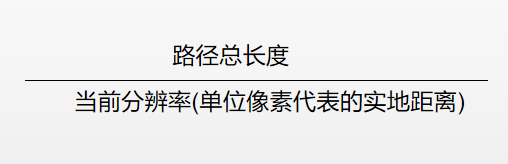
然后使用这个值去除以一个常量,这里我选的是100,也就是说箭头之间的距离,无论在那个分辨率下面,都是100像素长度。
接下来就是按照这个点位数进行迭代取点,核心的API就是getCoordinateAt ()作用是根据百分比取曲线上的点坐标。取到点的坐标之后直接做成要素,缓存到数组里。
核心:确定点位上箭头的方向

 //确定方向并绘制
  street.getGeometry().forEachSegment((start, end) => {
    points.forEach((item) => {
      let line = new LineString([start, end])
      let coord = item.getGeometry().getFirstCoordinate();
      let cPoint = line.getClosestPoint(coord);
      if (Math.abs(cPoint[0] - coord[0]) < 1 && Math.abs(cPoint[1] - coord[1]) < 1) {
        var myImage = new Image(117, 71);
        myImage.src = '/data/arrow.png';
        let dx=end[0] - start[0];
        let dy=end[1] - start[1];
        var rotation = Math.atan(dx/dy);
        rotation=dy>0?rotation:(Math.PI+rotation);
        vct.setStyle(new Style({
          image: new Icon({
            img: myImage,
            imgSize: [117, 71],
            scale: 0.15,
            rotation: rotation
          })
        }))
        vct.drawGeometry(item.getGeometry())
      }
    });
用作此例的一个透明背景的白色箭头
想要确定点位上箭头的方向,需要判定点位所在直线线段,根据直线线段的起始点和终点(注意是有序的)来计算得到需要旋转的角度。首先我们对路径的geometry上面的所有直线线段进行迭代(使用forEachSegment),针对每一个直线段,都判断一下前面获取到的点集合中,哪一个点在它上面,然后计算出线段的方向,将箭头图标旋转相应的角度,通过样式绘制在这个点位上。
基本的算法思想是这样的,但操作起来有个很实际的问题:在上一个我们获取点位的过程中,这些点的坐标是保留了一定精度的,也就是说,即便是原来就在某个线段上的点,如果截取了小数位,就不可能符合这个线段的直线方程!
所以在这里我用了一个技巧,利用OpenLayers提供的API getClosestPoint,计算点位到线段上最近一个点的坐标偏移量,如果这个偏移量足够小,我就认为点位在这个线段上了(实际上就是这么回事!)
      let cPoint = line.getClosestPoint(coord);
      if (Math.abs(cPoint[0] - coord[0]) < 1 && Math.abs(cPoint[1] - coord[1]) < 1) {
旋转的角度是通过xy的坐标差进行反正切之后再调整得到的:这里是反正切的象限与符号和偏转角度计算的关系,经过总结,得到代码中的调整公式。

        let dx=end[0] - start[0];
        let dy=end[1] - start[1];
        var rotation = Math.atan(dx/dy);
        rotation=dy>0?rotation:(Math.PI+rotation);

 最后把起点和终点的样式渲染上去:

    vct.setStyle(outStyle)
    vct.drawGeometry(new Point(street.getGeometry().getFirstCoordinate()))
    vct.setStyle(midStyle)
    vct.drawGeometry(new Point(street.getGeometry().getFirstCoordinate()))
    vct.setStyle(innerDot)
    vct.drawGeometry(new Point(street.getGeometry().getFirstCoordinate()));
    vct.setStyle(foutrStyle)
    vct.drawGeometry(new Point(street.getGeometry().getLastCoordinate()))
    vct.setStyle(fmidStyle)
    vct.drawGeometry(new Point(street.getGeometry().getLastCoordinate()))
    vct.setStyle(finnerStyle)
    vct.drawGeometry(new Point(street.getGeometry().getLastCoordinate()));
  })

 然后累加偏移量offset,在下一次渲染的时候微调点位的位置。这里有一个判断,如果offset超过了1,就重置,使得动画能够循环进行。最后显式调用render()函数,进行下一次渲染。

 offset = offset + 0.003
  //复位
  if (offset >= 1) offset = 0.001
  map.render()
})
完整代码:
所用道路数据为OpenLayers官方实例中jsts integrated所用素材,下载链接:
https://openlayers.org/en/latest/examples/data/geojson/roads-seoul.geojson
import { Map, View } from 'ol';
import OSM from 'ol/source/OSM';
import TileLayer from 'ol/layer/Tile';
import LineString from 'ol/geom/LineString';
import Point from 'ol/geom/Point';
import VectorSource from 'ol/source/Vector';
import VectorLayer from 'ol/layer/Vector';
import Feature from 'ol/Feature';
import GeoJSON from 'ol/format/GeoJSON'
import { getVectorContext } from 'ol/render';
import { Fill, Stroke, Circle, Style, Text, Icon } from 'ol/style';
import soul from './data/soul.json';

let tileLayer = new TileLayer({
  source: new OSM()
})
let map = new Map({
  target: 'map',
  layers: [
    tileLayer
  ],
  view: new View({
    center: [11936406.337013, 3786384.633134],
    zoom: 5,
    constrainResolution: true
  })
});

var vSource = new VectorSource()
var vLayer = new VectorLayer(
  {
    source: vSource,
  }
)
var geojsonFormat = new GeoJSON();
var features = geojsonFormat.readFeatures(soul, {
  dataProjection: "EPSG:4326",
  featureProjection: "EPSG:3857"
});
var street = features[16];
map.addLayer(vLayer);
map.getView().fit(street.getGeometry());

//some styles =========================================================================
var textStyle = new Style({
  text: new Text({
    font: 'bold 26px Mirosoft Yahei',
    placement: 'line',
    text: "江 南 大 街",
    fill: new Fill({
      color: '#000'
    }),
    offsetY:3,
    stroke: new Stroke({
      color: '#FFF',
      width: 2
    })
  })
})
var buttomPathStyle = new Style({
  stroke: new Stroke({
    color: [4, 110, 74],
    width: 28
  }),
})
var upperPathStyle = new Style({

  stroke: new Stroke({
    color: [0, 186, 107],
    width: 20
  }),
})
var outStyle = new Style({
  image: new Circle({
    radius: 18,
    fill: new Fill({
      color: [4, 110, 74]
    })
  })
})
var midStyle = new Style({
  image: new Circle({
    radius: 15,
    fill: new Fill({
      color: [0, 186, 107]
    })
  })
})
var innerDot = new Style({
  image: new Circle({
    radius: 6,
    fill: new Fill({
      color: [255, 255, 255]
    })
  })
})
var foutrStyle = new Style({
  image: new Circle({
    radius: 18,
    fill: new Fill({
      color: "#000"
    })
  })
})
var fmidStyle = new Style({
  image: new Circle({
    radius: 15,
    fill: new Fill({
      color: '#FFF'
    })
  })
})
var finnerStyle = new Style({
  image: new Circle({
    radius: 6,
    fill: new Fill({
      color: '#000'
    })
  })
})
street.setStyle(textStyle);
vSource.addFeature(street)
//some styles end =========================================================================

var offset = 0.01;
tileLayer.on('postrender', (evt) => {
  var vct = getVectorContext(evt);
  vct.drawFeature(street, buttomPathStyle)
  vct.drawFeature(street, upperPathStyle)
  let numArr = Math.ceil((street.getGeometry().getLength() / map.getView().getResolution()) / 100)
  var points = []
  for (var i = 0; i <= numArr; i++) {
    let fracPos = (i / numArr) + offset;
    if (fracPos > 1) fracPos -= 1
    let pf = new Feature(new Point(street.getGeometry().getCoordinateAt(fracPos)));
    points.push(pf);
  }

  //确定方向并绘制
  street.getGeometry().forEachSegment((start, end) => {
    points.forEach((item) => {
      let line = new LineString([start, end])
      let coord = item.getGeometry().getFirstCoordinate();
      let cPoint = line.getClosestPoint(coord);
      if (Math.abs(cPoint[0] - coord[0]) < 1 && Math.abs(cPoint[1] - coord[1]) < 1) {
        var myImage = new Image(117, 71);
        myImage.src = '/data/arrow.png';
        let dx=end[0] - start[0];
        let dy=end[1] - start[1];
        var rotation = Math.atan(dx/dy);
        rotation=dy>0?rotation:(Math.PI+rotation);
        vct.setStyle(new Style({
          image: new Icon({
            img: myImage,
            imgSize: [117, 71],
            scale: 0.15,
            rotation: rotation
          })
        }))
        vct.drawGeometry(item.getGeometry())
      }
    });
    vct.setStyle(outStyle)
    vct.drawGeometry(new Point(street.getGeometry().getFirstCoordinate()))
    vct.setStyle(midStyle)
    vct.drawGeometry(new Point(street.getGeometry().getFirstCoordinate()))
    vct.setStyle(innerDot)
    vct.drawGeometry(new Point(street.getGeometry().getFirstCoordinate()));
    vct.setStyle(foutrStyle)
    vct.drawGeometry(new Point(street.getGeometry().getLastCoordinate()))
    vct.setStyle(fmidStyle)
    vct.drawGeometry(new Point(street.getGeometry().getLastCoordinate()))
    vct.setStyle(finnerStyle)
    vct.drawGeometry(new Point(street.getGeometry().getLastCoordinate()));
  })

  offset = offset + 0.003
  //复位
  if (offset >= 1) offset = 0.001
  map.render()
})

<!DOCTYPE html>
<html>
  <head>
    <meta charset="utf-8">
    <title>Using OpenLayers with Webpack</title>
    <link rel="stylesheet" href="https://openlayers.org/en/latest/css/ol.css" type="text/css">
    <style>
      html, body {
        margin: 0;
        height: 100%;
      }
      #map {
        position: absolute;
        top: 0;
        bottom: 0;
        width: 100%;
      }
    </style>
  </head>
  <body>


    <div id="map"  class="map"></div>
    <script src="./amap_path.bundle.js"></script>

    </body>
</html>
时间仓促,代码中肯定还有很多可以改进的地方,比如将渲染过程函数化,关键数值作为参数,便于调整动画效果。另外,因为使用的是百分比截取,动画的速度在分辨率变化之后也会变快或者变慢,这也是一个需要改进的地方。
这个实例应用了大量的VectorContext绘制,利用VectorContext还可以绘制更多更炫的效果,感兴趣的可以一起研究一下。
 分类导航
分类导航